
Types of hydraulic directional control valve
2024-03-22Hydraulic control valves are used to control the pressure, flow and flow direction of oil in the hydraulic system so that the thrust, speed and movement direction of the actuator meet the requirements. According to their functions, hydraulic control valves are divided into three categories: directional valves, pressure valves and flow valves.
Directional control valve
Directional valve is a valve used to control the direction of oil flow. It is divided into one-way valve and reversing valve according to type.
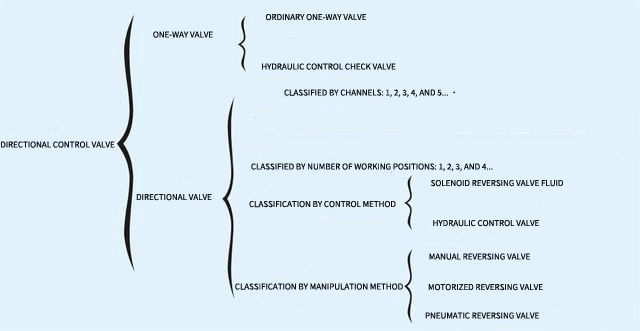
Types of directional control valves are as follows:
(1) One-way valve (check valve)
The one-way valve is a directional valve that controls the flow of oil in one direction and does not allow reverse flow. It is divided into ball valve type and poppet valve type according to the valve core structure, as shown in Figure 8-17.
Figure 8-18(b) shows a poppet check valve. The original state of the valve is that the valve core is lightly pressed on the valve seat under the action of the spring. During operation, as the pressure at the inlet oil pressure P increases, it overcomes the spring pressure and lifts the valve core, causing the valve to open and connect the oil circuit, so that oil flows in from the oil inlet and flows out from the oil outlet. On the contrary, when the oil pressure at the oil outlet is higher than the oil pressure at the oil inlet, the pressure of the oil presses the valve core tightly against the valve seat, blocking the oil passage. The function of the spring is to help the backflow oil hydraulically tighten the valve port when the valve is closed to strengthen the seal.
(2) Directional valve
The reversing valve is used to change the oil flow path to change the movement direction of the working mechanism. It uses the valve core to move relative to the valve body to open or close the corresponding oil circuit, thereby changing the working state of the hydraulic system. When the valve core and valve body are in the relative position shown in Figure 8-19, the two chambers of the hydraulic cylinder are blocked from pressure oil and are in a shutdown state. If a force from right to left is applied to the valve core to move it to the left, the oil ports P and A on the valve body are connected, and B and T are connected. The pressure oil enters the left chamber of the hydraulic cylinder through P and A, and the piston moves to the right; The oil in the cavity returns to the oil tank through B and T.
On the contrary, if a force from left to right is applied to the valve core to move it to the right, then P and B are connected, A and T are connected, and the piston moves to the left.
According to the different movement modes of the valve core, the reversing valve can be divided into two types: slide valve type and rotary valve type. Among them, the slide valve type reversing valve is more commonly used. The slide valve is divided according to the number of working positions of the valve core in the valve body and the oil port passage controlled by the reversing valve. The reversing valve has two-position two-way, two-position three-way, two-position four-way, two-position five-way and other types. , see Table 8-4. The different number of positions and passes are caused by the different combinations of the undercut grooves on the valve body and the shoulders on the valve core.
According to the spool control method, directional valves include manual, motorized, electric, hydraulic and electro-hydraulic types.
Pressure valve
Pressure valves are used to control the pressure of a hydraulic system, or use changes in pressure in the system to control the action of certain hydraulic components. According to different uses, pressure valves are divided into relief valves, pressure reducing valves, sequence valves and pressure relays.
(1) Relief valve
The overflow valve maintains a constant pressure in the controlled system or circuit through the overflow of the valve port, thereby achieving the functions of pressure stabilization, pressure regulation or pressure limiting. According to its structural principle, it can be divided into two types: direct-acting type and pilot type.
(2) Pressure Control Valves
The pressure reducing valve can be used to reduce and stabilize pressure, reducing the higher inlet oil pressure to a lower and stable outlet oil pressure.
The working principle of the pressure reducing valve is to rely on pressure oil to reduce pressure through the gap (liquid resistance), so that the outlet pressure is lower than the inlet pressure, and the outlet pressure is maintained at a certain value. The smaller the gap, the greater the pressure loss, and the stronger the pressure reduction effect.
Structural principles and symbols of pilot-operated pressure reducing valves. Pressure oil with a pressure of p1 flows in from the oil inlet A of the valve. After decompression through the gap δ, the pressure drops to p2, and then flows out from the oil outlet B. When the oil outlet pressure p2 is greater than the adjustment pressure, the poppet valve is pushed open, and part of the pressure in the oil chamber at the right end of the main slide valve flows into the oil tank through the poppet valve opening and the Y hole of the drain hole. Due to the effect of the small damping hole R inside the main slide valve core, the oil pressure in the oil chamber at the right end of the slide valve decreases, and the valve core loses balance and moves to the right. Therefore, the gap δ decreases, the decompression effect increases, and the outlet pressure p2 decreases. to the adjusted value. This value can also be adjusted via the upper pressure adjusting screw.
Direct acting pressure reducing valve
(3) Flow Control Valves
The flow valve is used to control the flow of liquid in the hydraulic system to achieve speed control of the hydraulic system. Commonly used flow valves include throttle valves and speed regulating valves.
The flow valve is a speed regulating component in the hydraulic system. Its speed regulating principle relies on changing the size of the flow area of the valve port or the length of the flow channel to change the liquid resistance, control the flow through the valve, and adjust the actuator (cylinder or motor). ) purpose of movement speed.
1) Throttle valve
The commonly used orifice shapes of ordinary throttle valves are as shown in the figure, including needle valve type, eccentric type, axial triangular groove type, etc.
Ordinary throttle valve adopts axial triangular groove type throttle opening. During operation, the valve core is evenly stressed, has good flow stability and is not easy to be blocked. Pressure oil flows in from the oil inlet p1, enters the hole a through the hole b and the throttling groove at the left end of the valve core 1, and then flows out from the oil outlet p2. When adjusting the flow rate, rotate the pressure regulating nut 3 to move the push rod 2 along the axial direction. When the push rod moves to the left, the valve core moves to the right under the action of the spring force. At this time, the orifice opens wide and the flow rate increases. When the oil passes through the throttle valve, there will be a pressure loss △p=p1-p2, which will change with the load, causing changes in the flow rate through the throttle port and affecting the control speed. Throttle valves are often used in hydraulic systems where load and temperature changes are small or speed stability requirements are low.
2) Speed regulating valve
The speed regulating valve is composed of a fixed difference pressure reducing valve and a throttle valve connected in series. The fixed difference pressure reducing valve can automatically maintain the pressure difference before and after the throttle valve unchanged, so that the pressure difference before and after the throttle valve is not affected by the load, thereby passing the throttle valve The flow rate is basically a fixed value.
The pressure reducing valve 1 and the throttle valve 2 are connected in series between the hydraulic pump and the hydraulic cylinder. The pressure oil from the hydraulic pump (pressure is pp), after being decompressed through the opening gap at the pressure reducing valve groove a, flows into groove b, and the pressure drops to p1. Then, it flows into the hydraulic cylinder through the throttle valve, and the pressure drops to p2. Under this pressure, the piston moves to the right against the load F. If the load is unstable, when F increases, p2 will also increase, and the valve core of the pressure reducing valve will lose balance and move to the right, causing the opening gap at slot a to increase, the decompression effect will weaken, and p1 will also increase. Therefore, the pressure difference Δp = pl-p2 remains unchanged, and the flow rate entering the hydraulic cylinder through the throttle valve also remains unchanged. On the contrary, when F decreases, p2 also decreases, and the valve core of the pressure reducing valve will lose balance and move to the left, so that the opening gap at slot a decreases, the decompression effect is enhanced, and p1 also decreases, so the pressure difference △p=p1-p2 remains unchanged, and the flow rate entering the hydraulic cylinder through the throttle valve also remains unchanged.