Basic structure and working principle of hydraulic system
2023-10-25一、Overview
The hydraulic system mainly includes main oil pump, hydraulic tank, filter, pressure reducing valve, relief valve, lifting cylinder, telescopic cylinder, tong cylinder, outrigger cylinder, hydraulic motor, and various hydraulic operations. valves and other components. Before the equipment leaves the factory, the pressures of the relief valve, pressure reducing valve and various pressure valves have been adjusted to ensure the safe operation of the hydraulic system, and users are not allowed to change them rashly during use.
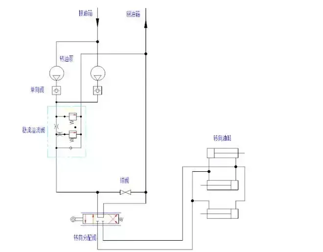
The hydraulic system includes a main hydraulic system and a steering hydraulic system, and the two systems share a hydraulic tank.
1.Main hydraulic system
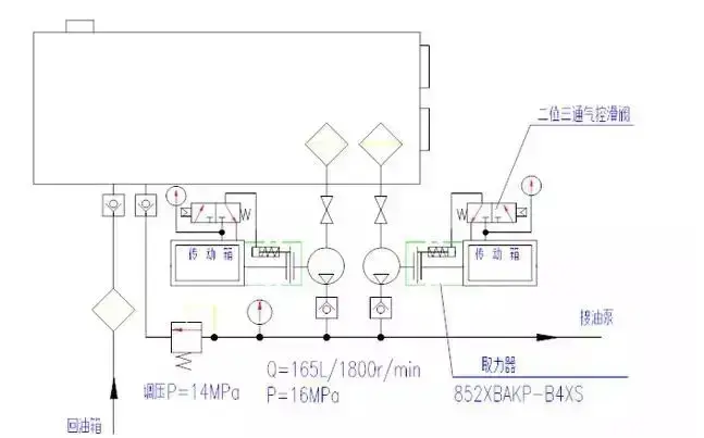
The main hydraulic system provides hydraulic power to the drilling rig during equipment adjustment and drilling repair operations. It is equipped with various valves to control the correct and safe operation of each hydraulic tool.
2.Steering hydraulic system
The steering hydraulic system provides hydraulic power for the hydraulic power steering of the front axle of the vehicle. It is equipped with various valves to control the pressure, flow direction and stable maximum flow of the hydraulic system, ensuring that the vehicle steering is light, flexible, safe and reliable.
3.Structural characteristics
The hydraulic system consists of:
¨ Main hydraulic system
¨ Steering hydraulic system
4.Main hydraulic system
Consists of the following components:
1) Hydraulic oil tank: stores, cools, precipitates and filters hydraulic oil. The fuel tank is installed with:
l There are two manhole covers installed on the top of the fuel tank. A hydraulic air filter is installed on the manhole cover in the oil return area of the fuel tank;
l Hydraulic air filter, filters the air flowing through the fuel tank, and filters the oil when the fuel tank is refueled;
l Liquid level gauges, 2, installed on the front side of the oil tank. There are two liquid level gauges, high and low. The high-level liquid level gauge displays the oil level after the derrick is lowered; the low-level liquid level gauge displays the oil level after the derrick is erected;
l Oil temperature gauge is installed on the front side of the fuel tank to measure the oil temperature in the tank. The normal operating oil temperature is between 30 and 70°C. There are two main oil return ports, which are set on the bottom plate of the fuel tank. They are equipped with one-way valves and are connected respectively. The main oil return pipe and the relief valve return port; the one-way valve automatically closes when repairing the hydraulic pipeline to prevent the loss of oil in the tank;
l The drain port is set on the bottom plate of the fuel tank and blocked with a plug; open the plug to drain the tank hydraulic oil;
l The suction port of the main oil pump is set on the front side of the fuel tank, and the main suction filter is installed;
l The steering oil pump suction port is set on the front side of the fuel tank, and a steering oil suction filter is installed;
l The oil return port of the steering system is set on the bottom plate of the fuel tank and equipped with a one-way valve. The one-way valve automatically closes when repairing the hydraulic pipeline to prevent the loss of oil in the tank;
2) Hydraulic oil pump: Single gear structure, 2 units, respectively installed on two hydraulic transmission power take-off boxes, driven by the torque converter pump wheel. When the engine rotates, the power take-off box can drive the oil pump. The power take-off box is equipped with a hydraulic clutch. When hydraulic action is required, the "liquid pump clutch" handle of the driller's control box can be operated and set to the "oil pump I close" position. The oil pump I is combined to output working pressure oil; the handle is set to "oil pump II". "Close" position, the oil pump II is connected and outputs working pressure oil;. The handle is in the neutral position, and both oil pumps disengage and stop.
3) Relief valve: pilot-operated structure, 2 sets, respectively installed at the oil outlet end of the main hydraulic oil pump. Adjust system pressure, prevent system overload, and protect system and component safety.
The structural principle of the relief valve: It is composed of a pilot valve and a main slide valve. The pilot valve part includes a valve body, a slide valve, a pressure regulating spring and other parts. There is a small hole a on the main valve slide valve, so that the imported pressure oil can enter the upper chamber B of the slide valve. When the hydraulic pressure acting on the poppet valve is less than the pretightening force of the spring, the pilot valve poppet valve will act under the action of the spring force. Since there is no oil flow in the valve body, the hydraulic pressure in the oil chambers at the upper and lower ends of the slide valve is equal. Therefore, the slide valve is in the extreme position of the lower end under the action of the upper end spring. The inlet and outlet of the relief valve is cut off by the slide valve, and the relief valve does not overflow; when the hydraulic pressure acting on the poppet valve increases to equal the spring force due to the increase in the inlet pressure of the relief valve, the poppet valve is pushed Open, the oil in the upper chamber B of the slide valve flows into the oil outlet of the valve through the oil return port b and the central through hole of the slide valve, and then overflows back to the oil tank. At this time, the pressure oil in the oil inlet of the relief valve flows from the small hole a. It is replenished upward to chamber B. Because there is a pressure loss when the oil passes through the small hole a, the pressure in chamber B is lower than the pressure at the oil inlet, and a pressure difference appears between the upper and lower ends of the slide valve. Therefore, under the action of the pressure difference between the upper and lower ends, the slide valve overcomes the spring force, and the slide valve's own weight and friction move upward, opening the inlet and return port of the relief valve, and the oil flows back to the tank. After the slide valve is opened, the fluid is driven by the hydraulic force. Affected, the inlet pressure P will continue to rise, and the slide valve will continue to move upward. When the force of the slide valve is balanced at a certain position, the inlet pressure of the relief valve will stabilize at a certain value, which is called the setting pressure of the relief valve.
4) Oil suction filter: self-sealing structure outside the tank, installed on the side of the hydraulic oil tank, the oil suction tube is immersed under the liquid level in the oil tank, and the filter head of the filter is exposed outside the oil tank; it is equipped with a self-sealing valve, a bypass valve, The filter element contaminates the transmitter and other devices. When replacing or cleaning the filter element, it can be disassembled and installed outside the tank. After the filter element is removed, the self-sealing valve automatically closes to prevent oil from flowing out of the tank. Bypass valve, when the filter element is clogged, the machine must not be shut down immediately for maintenance. The oil can be circulated through the bypass valve, and the machine can be shut down to clean or replace the filter element at the right time. Pressure difference indicator is a mechanical visual inspection structure. If the filter element is clogged, it will affect the oil pressure difference and the pointer will swing. , when it points to the red area, the machine should be shut down for cleaning or the filter element should be replaced. A ball valve is installed at the outlet of the filter to close it during maintenance and repair of the hydraulic pipeline to prevent the loss of oil in the tank.
5) Return oil filter: Equipped with a bypass valve and a pressure difference indicator. The filter filters solid impurities in the hydraulic oil, prevents impurities in the pipeline from entering the tank, and keeps the system oil clean; the bypass valve is used when the filter element is clogged. After that, it is not allowed to shut down the machine immediately for maintenance. The oil can be circulated through the bypass valve, and the machine should be shut down to clean or replace the filter element at the right time. The pressure difference indicator is a mechanical visual inspection structure. If the filter element is clogged, which affects the oil pressure difference, the indicator pile stretches out and points to the red area. When necessary, the machine should be shut down to clean or replace the filter element.
7) Lifting oil cylinder: three-stage composite oil cylinder structure, equipped with one-way throttle valve; lifting and landing derrick, one-way throttle valve to prevent gravity overspeed during the derrick landing process, and protect the safety of derrick lifting and landing. This machine is equipped with double lifting cylinders.
l Structure and working principle: The structure consists of cylinder, first-level piston, second-level piston, third-level piston, guide ring, sealing ring and other parts. The cylinder head is equipped with a pin ear plate, which is connected to the fixed ear plate on the frame cross beam by a pin. The third-stage piston rod is connected to the derrick lower body door frame pin in the same way. The first and second-level plungers have a one-way action structure. Under the action of hydraulic oil, the plunger extends out with power and retracts by its own weight when returning. The third-level piston has a two-way action structure. Under the action of hydraulic oil, the third-level piston Piston powered extension and retraction. The lifting cylinder is equipped with three oil ports, P1, P2 and P3. Oil port P1 is located at the cylinder head, connecting the plunger working chamber and the third-stage piston rodless chamber. There is a one-way throttle valve in the oil passage; oil port P2 is located at the third-stage piston rod, connecting the third-stage piston rodless chamber. There is a throttle hole in the rod cavity and the oil passage; the oil port P3 is located at the third-stage piston rod, connecting the plunger working chamber and the third-stage piston rodless chamber, and connected with the P1 oil passage. There is a throttle hole in the oil passage. A vent hole is provided at the third-stage piston cylinder head of the oil cylinder, and a vent plug is installed on it.
l Discharge air: Before each lifting and landing of the derrick, the air in the lifting cylinder and telescopic cylinder should be completely discharged. Hydraulic oil contains air, and leakage in the pipeline results in air in the cylinder. When the lifting cylinder and telescopic cylinder are parked for a long time, air will accumulate in the upper part of the cylinder. When the derrick is raised and lowered, the probability of accidents will be increased, air will be discharged, and hidden dangers of accidents will be eliminated.
l System pipeline air discharge: Open the needle valve E on the six-joint valve control panel to form a smooth circuit for the lifting cylinders P1 and P3, and connect the oil return pipeline. Lift the lifting cylinder control valve handle, the hydraulic oil of the oil pump enters the lifting cylinder through P1, and then returns to the oil tank through P3. The hydraulic system runs without load; the hydraulic system runs without load for 5 to 10 minutes, eliminate the leakage in the pipeline and the lifting cylinder gas.
l Discharge the air from the rod cavity of the third-stage piston of the lifting cylinder: close the needle valve E, and the lifting cylinders P1 and P3 form a closed circuit. Slightly lift the handle of the lifting cylinder control valve, supply pressure oil to the lower chamber of the lifting cylinder, control the oil pressure at 2~3MPa, open the bleed plug at the third-stage piston cylinder head of the cylinder, and discharge the air in the lifting cylinder.
l System leakage inspection: Slightly lift the lifting cylinder control valve, supply pressure oil to the lower chamber of the lifting cylinder, slowly lift the derrick, leave 100~200mm away from the front bracket of the derrick, stop lifting, and keep the derrick in the state for 5 minutes. Check the hydraulic system and pipelines, there should be no leakage anywhere; observe the derrick, there should be no obvious whereabouts.
l Safety mechanism: The derrick is heavy, and there is a greater chance of accidents when lifting and lowering the derrick. Pay more attention during operation and strictly follow the operating procedures. Multiple safety mechanisms are set up for the safe lifting cylinder. Even if the lifting cylinder control valve fails or the hydraulic hose is ruptured and damaged, the lifting cylinder will effectively slow down the derrick lowering speed and prevent major accidents.
l Lifting derrick: Hydraulic oil enters the working chamber of the oil cylinder from the P1 port through the one-way valve. The first-level plunger extends first. After reaching the position, the second-level plunger and the third-level piston rod extend in sequence. The third-level piston has a rod. The oil in the cavity returns through P2. Since the P2 port is equipped with a throttling hole, when the third-stage piston extends, the opening of the control valve should be reduced and the extension speed should be slowed down. Otherwise, the pressure of the hydraulic system will increase;
l Lower the derrick: Hydraulic oil enters the rod cavity of the third-stage piston from P2, pushing the piston to retract. The oil in the rodless cavity returns to the oil through the P1 throttle, and the cylinder retracts slowly to prevent gravity overspeed; The retraction sequence of each plunger and piston is: first, the third-stage piston retracts. After reaching the position, the second-stage and first-stage plungers retract in sequence. When the secondary and primary plungers retract, they fall back by their own weight without supplying hydraulic oil to the cylinder. At this time, the engine speed can be reduced and the operating handle slowly returns to the derrick.
8) Telescopic cylinder, hydraulic telescopic two-story derrick.
l Structural composition: Extra long plunger cylinder, with a total cylinder length of 14 to 16m. There is an oil port at the end of the plunger, and a one-way throttle valve is installed in the oil passage; the cylinder head is equipped with a bleed plug. The oil cylinder body is fastened to the upper body of the derrick with U-shaped bolts, and the top is pressed into the seat ring of the derrick beam. The lower part of the plunger rod is equipped with a connecting plate, which is bolted to the beam of the lower body of the derrick.
l Work process. The derrick on the second floor is extended, and the control valve of the telescopic oil cylinder is operated to lift up. The pressure oil enters the cylinder through the oil port at the end of the plunger rod, the one-way valve, and the hollow plunger, pushing the cylinder to extend, driving the upper body of the derrick to rise along the track. The derrick is in place and the locking pin mechanism is automatically locked. The second-floor derrick is retracted, and the safety pin is manually released. First, the telescopic cylinder control valve is operated to lift up, so that the second-floor derrick slowly rises about 200mm. The locking pin mechanism automatically unlocks, and then the telescopic cylinder control valve is operated to push down, and the hydraulic oil in the cylinder is The pressure generated by the self-weight of the second-story derrick flows out of the cylinder through the throttle port and the oil port at the end of the plunger. The second-story derrick falls. The falling speed is adjusted by the opening degree of the one-way throttle valve and the telescopic cylinder control valve.
l Safety mechanism: The derrick on the second floor is heavier, and there is a greater chance of accidents when lifting and lowering the derrick. Pay more attention during operation and strictly follow the operating procedures. The safety telescopic cylinder is equipped with a one-way throttle valve. Even if the cylinder control valve fails or the hydraulic hose is ruptured and damaged, the cylinder will effectively slow down the derrick's descent speed and prevent major accidents.
l Exhaust air: After the cylinder has been placed for a period of time, air will seep in from the seal. The newly installed cylinder has more air inside. Therefore, before each operation of the telescopic cylinder, the air in the telescopic cylinder must be discharged to prevent the expansion process of the cylinder. Crawling. Slightly lift the handle of the lifting cylinder control valve, supply pressure oil to the telescopic cylinder, and control the oil pressure at 2 to 3 MPa. Open the vent plug at the top of the cylinder to discharge the air in the telescopic cylinder. After draining, tighten the nut. Do not move while deflating. Open the derrick safety latch.
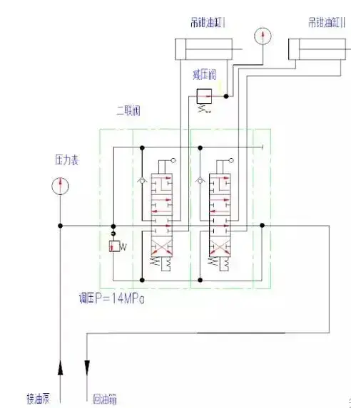
9) Clamp cylinder: The cylinder has a two-way piston structure, and buffer devices are provided at both ends of the cylinder head and cylinder cover to prevent hydraulic impact of the cylinder. When the piston rod of the oil cylinder retracts, the cat's head rope of the lifting tong is tightened to tighten and loosen the drill string thread; the piston rod extends and the cat's head rope returns.
10) Hydraulic small winch: planetary reduction mechanism, equipped with brake and balance valve, it is safe to lift objects and can hover in the air.
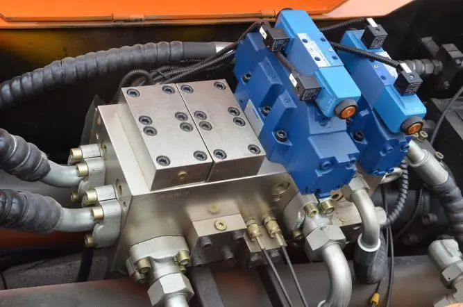
11) Double valve: Installed at the lower part of the driller's control box, it consists of an oil inlet valve plate, an oil return valve plate and two working valve plates. The oil inlet valve piece is equipped with a safety valve to adjust the working pressure entering the double valve. Loosen and tighten the nut, and twist the adjusting screw to change the adjusting pressure of the safety valve. When screwing in, the adjusting pressure increases, and when screwing out, the adjusting pressure decreases. Note that after adjustment, tighten the back cap and lock the adjusting nut. The working valve plate is manually controlled.
A. Lifting tong cylinder valve I: Controls the lifting tong I cylinder to extend and retract to loosen and tighten the anchor head rope. The valve core is set with a floating valve position to form a differential cylinder circuit. The oil pump oil and the rod cavity oil enter the rodless cavity of the oil cylinder at the same time, causing the piston rod to quickly extend; the valve core spring returns, release the handle, and the valve core automatically returns In the neutral position, the cylinder movement stops.
B. Lifting tong cylinder valve II: Controls the lifting tong II cylinder to extend and retract to loosen and tighten the anchor head rope. The valve core is set with a floating valve position to form a differential cylinder circuit. The oil pump oil and the rod cavity oil enter the rodless cavity of the oil cylinder at the same time, causing the piston rod to quickly extend; the valve core spring returns, release the handle, and the valve core automatically returns In the neutral position, the cylinder movement stops.
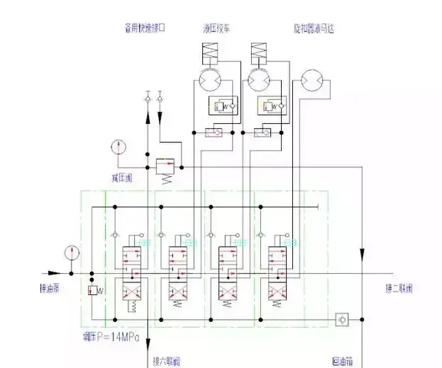
13) Six-joint valve: installed on the hydraulic control box at the rear left side of the frame. It consists of an oil inlet valve plate, an oil return valve plate and six working valve plates. The oil inlet valve piece is equipped with a safety valve to adjust the working pressure entering the six-joint valve. Loosen and tighten the nut, and twist the adjusting screw to change the adjusting pressure of the safety valve. When screwing in, the adjusting pressure increases, and when screwing out, the adjusting pressure decreases. Note that after adjustment, tighten the back cap and lock the adjusting nut.
- Front right outrigger cylinder valve: controls the right outrigger cylinder at the front of the frame, raises and lowers the frame, and adjusts the level of the frame. The valve core spring returns, release the handle, the valve core automatically returns to the neutral position, and the cylinder movement stops.
- Front left outrigger cylinder valve: controls the left outrigger cylinder at the front of the frame, raises and lowers the frame, and adjusts the level of the frame. The valve core spring returns, release the handle, the valve core automatically returns to the neutral position, and the cylinder movement stops.
- Rear right outrigger cylinder valve: controls the right outrigger cylinder at the rear of the frame. Raise, lower and level the frame. The valve core spring returns, release the handle, the valve core automatically returns to the neutral position, and the cylinder movement stops.
- Rear left outrigger cylinder valve: controls the left outrigger cylinder at the rear of the frame. Raise, lower and level the frame. The valve core spring returns, release the handle, the valve core automatically returns to the neutral position, and the cylinder movement stops.
- Lifting cylinder valve: controls the movement of the lifting cylinder to raise and lower the overall derrick. The valve core spring returns, release the handle, the valve core automatically returns to the neutral position, and the cylinder movement stops. Both output oil ports are equipped with overload valves to limit the pressure entering the oil cylinder and improve the safety of derrick operation.
- Telescopic oil cylinder valve: controls the action of the telescopic oil cylinder to extend and retract the second-story derrick. The valve core lock pin is positioned and the handle is released. The valve core still stays in the working position and the oil cylinder continues to move. Both output oil ports are equipped with overload valves to limit the pressure entering the oil cylinder and improve the safety of derrick operation.
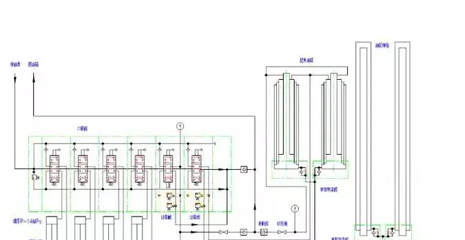
13) Six-joint valve: installed on the hydraulic control box at the rear left side of the frame. It consists of an oil inlet valve plate, an oil return valve plate and six working valve plates. The oil inlet valve piece is equipped with a safety valve to adjust the working pressure entering the six-joint valve. Loosen and tighten the nut, and twist the adjusting screw to change the adjusting pressure of the safety valve. When screwing in, the adjusting pressure increases, and when screwing out, the adjusting pressure decreases. Note that after adjustment, tighten the back cap and lock the adjusting nut.
A. Front right outrigger cylinder valve: controls the right outrigger cylinder at the front of the frame, raises and lowers the frame, and adjusts the level of the frame. The valve core spring returns, release the handle, the valve core automatically returns to the neutral position, and the cylinder movement stops.
B. Front left outrigger cylinder valve: controls the left outrigger cylinder at the front of the frame, raises and lowers the frame, and adjusts the level of the frame. The valve core spring returns, release the handle, the valve core automatically returns to the neutral position, and the cylinder movement stops.
C. Rear right outrigger cylinder valve: controls the right outrigger cylinder at the rear of the frame. Raise, lower and level the frame. The valve core spring returns, release the handle, the valve core automatically returns to the neutral position, and the cylinder movement stops.
D. Rear left outrigger cylinder valve: controls the left outrigger cylinder at the rear of the frame. Raise, lower and level the frame. The valve core spring returns, release the handle, the valve core automatically returns to the neutral position, and the cylinder movement stops.
E. Lifting cylinder valve: controls the movement of the lifting cylinder to raise and lower the overall derrick. The valve core spring returns, release the handle, the valve core automatically returns to the neutral position, and the cylinder movement stops. Both output oil ports are equipped with overload valves to limit the pressure entering the oil cylinder and improve the safety of derrick operation.
F. Telescopic oil cylinder valve: controls the action of the telescopic oil cylinder to extend and retract the second-story derrick. The valve core lock pin is positioned and the handle is released. The valve core still stays in the working position and the oil cylinder continues to move. Both output oil ports are equipped with overload valves to limit the pressure entering the oil cylinder and improve the safety of derrick operation.
2.Steering hydraulic system
Consists of the following components:
1) The steering oil pump is installed on the power take-off port of the engine. The engine rotates and drives the oil pump to work.
2) The oil suction filter has a self-sealing structure outside the tank. It is installed on the side of the hydraulic oil tank. The oil suction tube is immersed under the liquid level in the oil tank. The filter head is exposed outside the oil tank. It is equipped with a self-sealing valve, a bypass valve and a filter element. When replacing or cleaning the filter element of devices such as pollution transmitters, it can be done outside the tank. It is easy to disassemble and install, and the oil in the tank will not flow out.
3) The overflow and flow stabilizing valve adjusts the system pressure, prevents system overload, and protects the safety of the system and components; the oil pump operates at high speed, and when the flow rate is too large, the flow is diverted back to the tank to ensure the highest stable flow rate of the system. See figure (relief and flow stabilizing valve)
4) The steering distribution valve follows the direction of the steering wheel, controls the flow direction and flow of hydraulic oil, supplies the steering cylinder, and pushes the front axle wheels to turn left and right. See Figure (Steering Distribution Valve)
5) Steering cylinder, two-way piston cylinder, one for each of the front three axles; the piston rod head is connected to the steering knuckle arm to control the wheel angle. See picture (steering cylinder)
- The ball valve is connected between the pressure pipeline and the oil return pipeline. When the drilling rig is in operation, open the ball valve to unload the system and protect system components.
